Keli Motor Group Search

Terms of the Motor
The terms of the classification of the motor
1. Shaded pole motor
It is a kind of single-phase AC motor, usually using cast aluminum rotor with cage chute. According to the different shape and structure of the stator, it is divided into salient pole shaded pole motor and hidden pole shaded pole motor.
2. Universal motor
An electromagnet excitation beam type DC motor that generates excitation beam through an electromagnet, in which the excitation winding and the armature winding are in series.
This characteristic is that the rotation speed will change drastically with the change of load. When starting or at low speed, a large torque will occur. When the load decreases, the rotation speed will increase.
This characteristic is generally referred to as the series excitation characteristic. It was mainly used for specific purposes such as trams and elevators. It has now been replaced by a variable speed control method for induction motors and synchronous motors using frequency converters.
This type of motor can also be used with AC. However, if a motor designed as a DC motor is used with AC, the loss such as iron loss will increase, so it will generate abnormal heat.
3. Stepper motor
Stepper motor is an open-loop control motor that converts electrical pulse signals into angular displacement or linear displacement. It is an induction motor.
Stepper motors can be easily controlled by digital signals. In addition to industrial applications and computer peripherals, they are also used in office equipment such as fax machines and copiers. Stepper motors are generally divided into HB hybrid stepper motors and PM type stepper motors.
4. AC servor motor
Motors that work with AC power are called AC motors, and AC servor motors are divided into induction motors and brushless DC motors. The brushless DC motor is called an AC motor mainly because an alternating voltage with voltage variation is applied to the coil of the rotating brushless DC motor.
5. PM motor
Motors using permanent magnets, which are divided into brushed DC motors and brushless DC motors.
6. Brushless DC motor
Brushless DC motor overcomes the shortcomings of brush DC motor of brush wear and electrical interference by removing the brush. It has the characteristics of maintenance-free, miniaturization, high motor efficiency and good heat dissipation performance. It is also called commutatorless motor and brushless motor.
The terms of characteristics of the motor
1. Holding torque
When the stepper motor is stopped in the energized state, even if an external force is applied, due to the attractive force between the rotor and the stator, the stop position can still be maintained. This torque that can resist the external force is called the holding torque.
2. Stop torque
When the PM type and HB type stepper motor is not energized, it also has a certain degree of holding torque under the effect of the attraction of the rotor magnet, which is called the stop torque
3. Pulse frequency
The speed of a stepper motor is generally expressed in pulses per second (steps) [pps]. Also called pulse rate or step rate.
4. surge
Refers to the working interval where the fan air volume is periodically in an unstable state. Noise will also increase, so choose a fan that will not surge is needed.
5. Pole number
The so-called pole number or pole refers to the number of magnetic poles appearing on the face after the motor is cut in a direction perpendicular to the axis.
Basically, the number of poles is even (2,4,6,8 ...), and the winding method is divided into distributed winding and centralized winding. The centralized winding is suitable for brushless motors, and the number of poles can be easily changed according to the wiring of the coil. For 6-coil stators, 2-pole, 4-pole or 8-pole wiring can be performed. But the motor that has been completed cannot change the number of poles to 4 or 8 poles. In the 9-slot rotor, 12-pole distributed winding is mostly used, which is suitable for induction motors, and the number of poles must be determined before winding.
Before the advent of 2-pole brushless motors running at high speeds of 50 or 60 revolutions per second, small motors were mostly 4-poles, and their wiring was complicated. It was difficult to call them distributed windings or centralized windings. Induction motor poles can be changed by changing the wiring This is a technology that changes the synchronization speed to achieve dual speed operation.
6. Protection level
According to the structure of the motor housing, the protection methods are divided into the following types.
-Open type: unprotected structure
-Protection type: The housing has an opening, and the external air around the motor can circulate with the internal structure (IP2X)
-Fully enclosed type: the housing is closed to prevent external air around the motor from entering the motor (IP4X)
-Drip-proof type: A structure with waterproof protection (IPX2)
-Drip-proof protection type: a structure that satisfies both the protection type and the drip-proof type (IP22)
-Fully enclosed external fan type: Fully enclosed type with fan. Structure for cooling the shell surface
-Fully closed self-cooling type: fully closed type without fan. Natural cooling method
-Fully enclosed external force ventilation type: Fully enclosed type without fan, the external air has a fixed air flow, which has the same cooling function as the external fan
-Explosion-proof type: It can be used normally in places with explosive gas. Divided into safety enhanced explosion-proof type, pressure-proof explosion-proof type, etc.
-Indoor type: the type used in the house
-Outdoor type: The type that can be used outdoors even after the sealing material is installed
The terms of structure of the motor
1. Coil
In a motor, a wire is generally wring on a magnetic pole and is called a coil, and each coil is connected to each other to form a winding.
2. Rotor
The rotating part. Also called the rotor.
3. Iron core
The so-called iron core is a magnetic channel. As the literal meaning is, the material is iron and silicon is added, commonly known as silicon steel. In addition, iron that combines two magnets with magnetic flux is generally called a yoke.
In the motor, the iron core is divided into a stator iron core and a rotor iron core, and the magnetic circuit is formed by the gap between the two.
The magnetic poles of the stator core that constitutes the excitation circuit of the electromagnet excitation type DC motor are excited by direct current. Therefore, the iron core does not need to have a laminated structure, and soft steel can be used.
On the other hand, the magnetic flux of the rotor core constituting the armature circuit changes when it rotates. Therefore, a laminated core is used, and the magnetic pole of a small DC motor generally uses a permanent magnet.
Since the excitation is performed by AC, the stator core of the synchronous motor, the stator of the induction motor and the iron core of the rotor are preferably laminated iron cores.
4. Shaft
Refers to “the output shaft”.
5. Bearing
Bearings can be used to reduce wear on rotating parts.
The terms of evaluating the motor
1. Motor efficiency
The efficiency of a motor in converting electricity into power refers to the ratio of mechanical output to input power expressed as a percentage.
2. N-T characteristics
The motor characteristic diagram showing the relationship between the rotation speed and torque is also called "TN characteristic" and "NT characteristic". Together with the TI characteristic diagram showing the relationship between torque and motor current, it is collectively called the TI-TN characteristic diagram.
3. TI characteristics
The motor characteristic diagram showing the relationship between the torque and the motor current, together with the TN characteristic diagram showing the relationship between the torque and the rotation speed, is collectively called the TI-TN characteristic diagram.
4. TN characteristics
The motor characteristic diagram showing the relationship between the rotation speed and torque is also called "TN characteristic" and "NT characteristic". Together with the TI characteristic diagram showing the relationship between torque and motor current, it is collectively called the TI-TN characteristic diagram.
5. P-Q curve
The fan air volume-static pressure characteristic diagram (P-Q curve) is a curve that represents the relationship between the air volume and the static pressure caused by the loss of pressure acting on the air inlet and air outlet. When the loss due to pressure (static pressure) is 0, it is called the maximum air volume, and when the pressure loss (static pressure) is maximum, it is called the maximum static pressure.
Basic knowledge-Major categories-Servo motor
1. Definition:
The servo motor is an automatic control system that allows for precise control of the object's position, orientation, state and other output controlled quantities by controlling the input quantity (given value). The etymology of Servo comes from Latin language “Servus”, which means to faithfully execute the master's orders.

Servo system generally consists of Servo Drive and Servo Motor. The Servo Drive provides Servo Motor the voltage and current to operate, and also control the output torque, output speed and stop position of the motor by adjusting the voltage (current) supplied to the motor. Types of Servo Motors are classified into different types based on their construction, such as the AC servo motor, and DC servo motor.
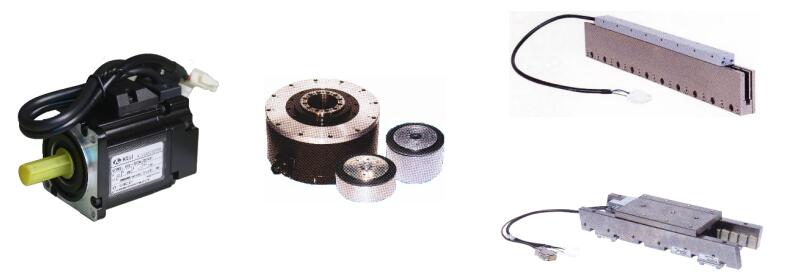
2. characteristic:
1. High precision
The servo motor is a closed-loop mechanism. Servo drive adjusts and controls the operation of motor according to the positional feedback of encoder. And because of the encoder, missed steps which is a common defect in step motor, would not appear in servo motor. Besides, encoder can adjust the output torque, speed, rotation angle and so on based on the status of load, which achieve compliance with instructions. The encoder with great precision can achieve very precise control and position. For example, the optical encoder commonly used in the industry has a single-turn resolution of 23bit, and the unit positioning accuracy is 1/8388608 after conversion, which divides a 360 degree circle of the motor into 8388608 parts.
2. Various control mode
Most servo motors support 6 control modes: position control, speed control, torque control, position-speed control switch, position-torque control switch and speed-torque control switch. According to the requirements of the equipment, different control methods can be selected flexibly to achieve different control effects.
3. widely used
The application of servo motor covers a wide rang. Common servo motors on the market from a few watts to dozens of kilowatts are available for related products.
4. High efficiency and long life
Due to the special closed loop control system, Servo Motor is able to control the motor output according to the status of load. With small heat, its efficiency is obviously higher than the ordinary motor, and the general conversion efficiency can reach more than 90%. It always has been the useful tool to be energy-efficient for the company. At the same time, because the servo motor (AC) belongs to brushless motor, the motor drive current commutation which is carried out in the driver with electronic components. Compared with the traditional brush of brushed motor, which is easy to wear, the servo motor is maintenance-free, with a life span of more than 10 years, and even has been used for decades and can operate normally.
3. Application
Servo motors have been around for a long time and are utilized in many applications which is used in machinery, metallurgy, electric power, petrochemical, shipbuilding, aerospace, construction, transportation, agriculture, scientific research and testing, etc. According to the classification of equipment, it can also be divided into machine tools, printing equipment, medical equipment, semi-conductive manufacturing equipment, 3C product manufacturing equipment, injection molding equipment, food processing equipment, security equipment, packaging equipment, textile equipment, laser processing equipment, robots, automatic production lines, etc.
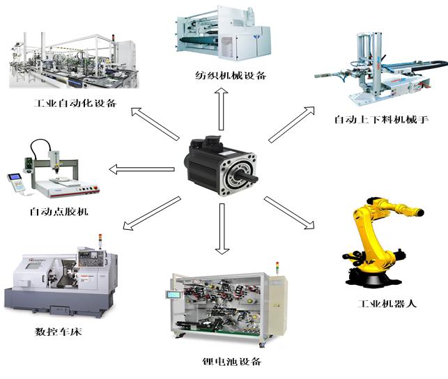
4. Basic construction
Servo motor is comprised of several parts namely a rotor, stator, holding brake, and encoder
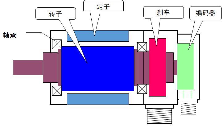
The rotor is the rotating part of the motor, which is composed of a shaft and a permanent magnet (rotor core). The stator is the fixed part of the motor, which is generally composed of bearing, motor housing, stator core and winding. Brake (holding brake) is an optional accessory, which is generally installed at the back of the motor. It is used to keep the rotor position of the motor when the motor is power off, so as to prevent unnecessary damage caused by the load dragging the motor to rotate due to the gravity effect of the load. The encoder plays the role of provide the positional feedback of motor rotor, which is equivalent to the servo motor eye.
5. Working principle
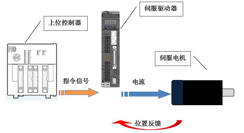
1.How the system works
Servo system is composed of servo driver and servo motor. Servo driver receives the control commands from the controller. At the same time servo drive will compare the control commands with the feedback about motor status from encoder. When there is a difference between these two parameters, servo driver will adjust the current supplied to the motor, control the motor output torque to make the motor speed up or slow down. Finally the motor state will be consistent with input instruction.
2.Working principle of servo driver
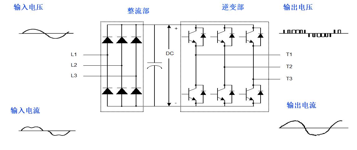
The driver consists of two circuits: the power supply part and the controlling part
Power supply part: This part supply current and drive the motor, whose duty is to pass the electricity to the motor. Further explain that the commercial power supply is rectified as shown in the figure below. There are two parts; converter part and inverter part. Converter part is used to producing DC power and inverter part is used to input UVW phase power according to the motor turning angle
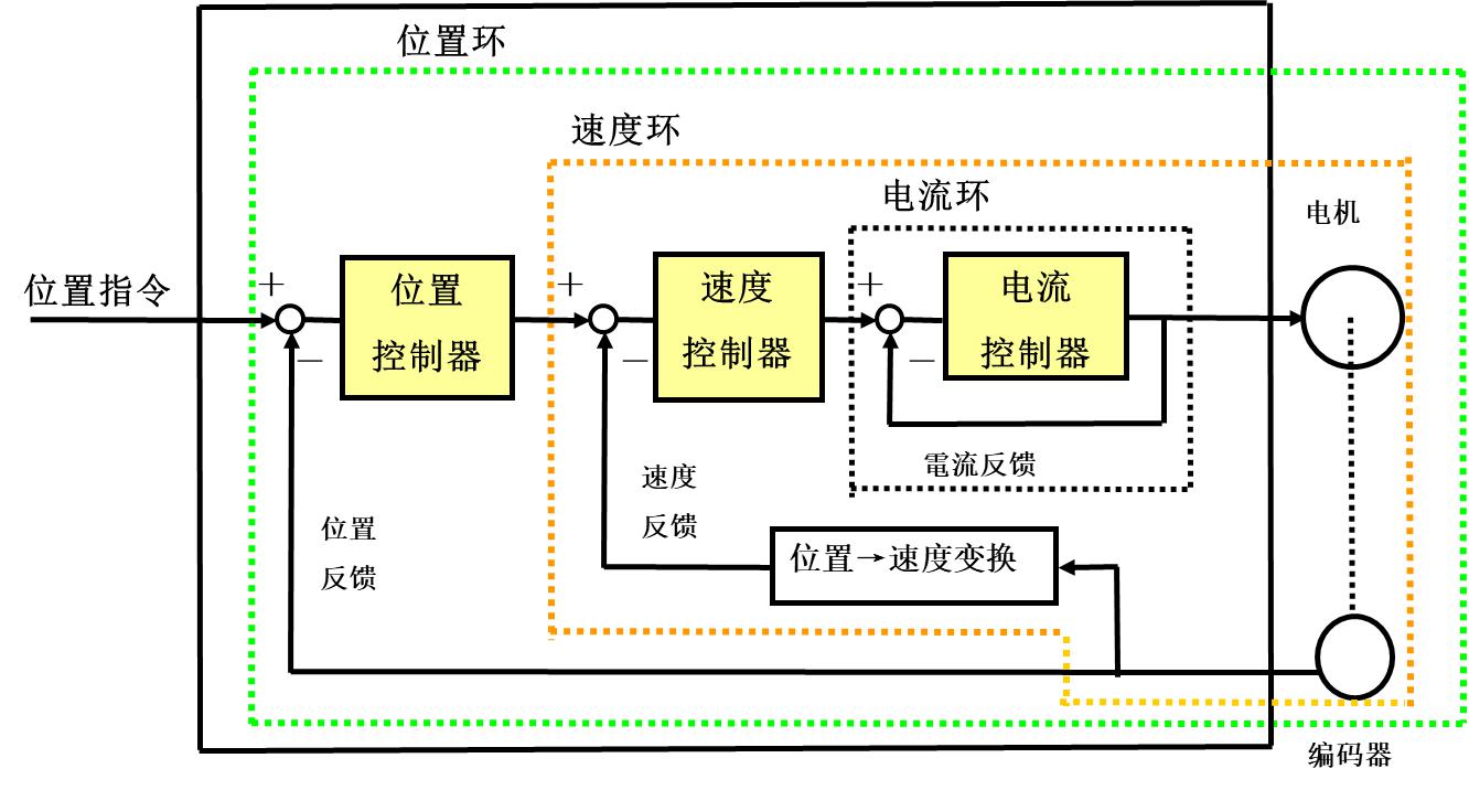
Controlling part: Depending on the control mode selected by the customer, the driver will open and choose the relevant control function modules. For example, in the current loop control mode, the driver is only responsible for controlling the motor's output torque following the command changes, and does not control the motor's speed and position. Under the position loop control mode, the driver needs to control the output torque and motor speed of the motor at the same time. So as to achieve the purpose of controlling the position of the motor.
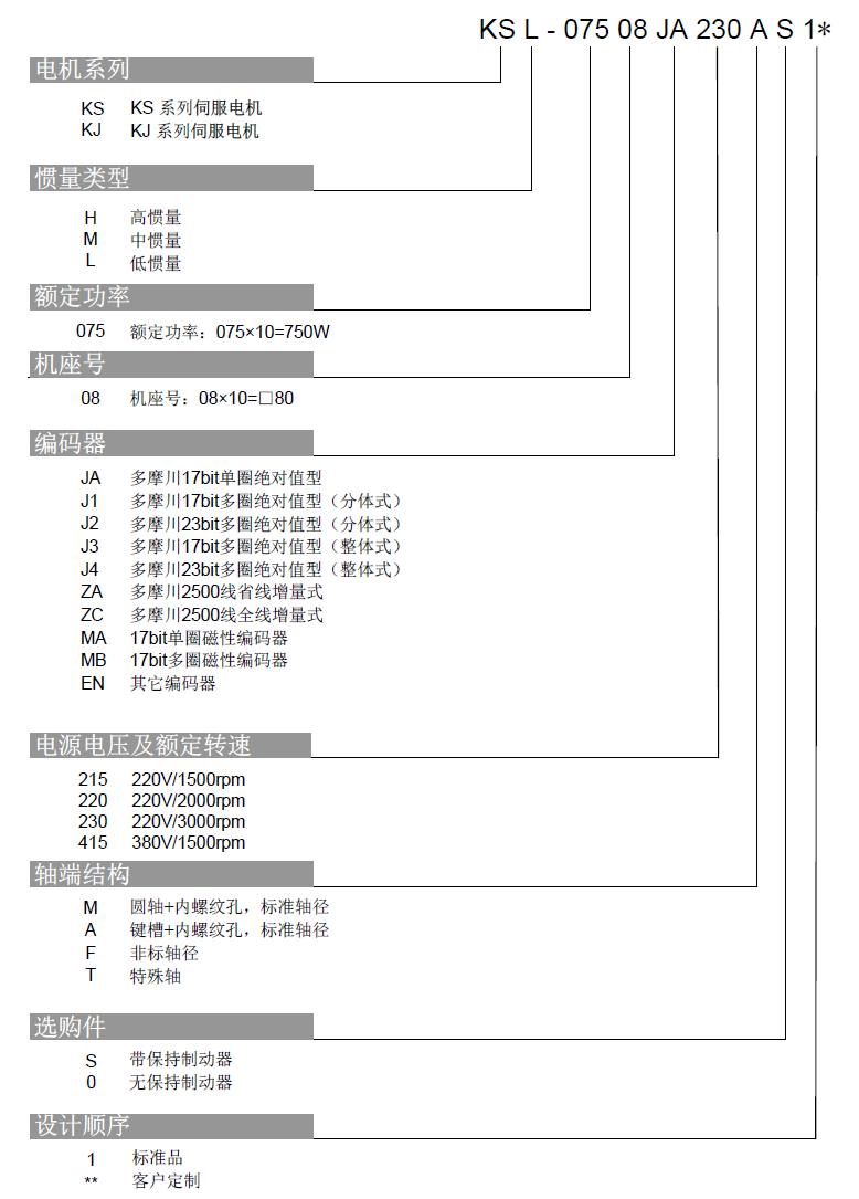
3.naming rule
Servo motor naming rules
Basic knowledge of motor-Classification-Shade pole motor
1. Overview
The shaded pole motor is one of the simplest type of miniature single-phase induction motor. Because it has the advantages of simple structure, convenient manufacture, low cost, reliable operation, strong overload capacity, convenient maintenance and so on, it is widely used in various low-power driving devices. The disadvantage is that the running performance and starting performance are poor, and the efficiency and power factor are reduced. It is usually used for small-capacity occasions with no-load or light-load starting, such as electric fans.
2. Working principle
A motor without a shaded pole ring and only a main winding has no starting torque and cannot be used in practice. In order to obtain starting torque, the measures of additional auxiliary winding are used. This winding is not powered by an external power supply, but by maintaining an off angle of θ <90 between it and the main winding axis, see Figure 1. After the main winding power-on, a part of the main magnetic flux Φm ' will pass through this shaded coil, and the induced potential generates a current. The shaded coil, like the secondary winding of the transformer produces demagnetizing flux Φk, and after synthesis with Φm ', it will be Φs in the shaded pole section, and finally determines the potential Ek on the shaded pole ring. So that Φm and Φs with different time phases are pulsed at different sections between the main pole and the shaded pole, to form an elliptical magnetic field and generate a starting torque. Under the condition that the rotor is closed, the rotor will start. Since Φm is ahead of Φs, the magnetic field moves from the leading magnetic flux to the lagging, so the rotation direction of the motor is clockwise from the main pole to the shaded pole.
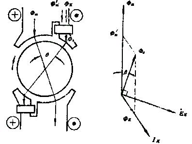
(a)Working principle (b) Vector Diagram
Figure 1 is the principle and vector diagram of shaded pole motor
3. Technical indicators and Term
3.1 Technical indicators
Rated power
Rated voltage
Rated current
Rated speed
3.2 Term
3.2.1 fficiency: The ratio of motor output power to input power.
3.2.2 Power factor COSØ: The ratio of the effective power input to the apparent power of the motor.
3.2.3 Starting torque Tst: Torque generated by the motor at rated voltage, rated frequency and when the rotor is blocked.
3.2.4 Maximum torque Tmax: The maximum torque generated when the motor does not drop suddenly under the rated voltage, rated frequency and operating temperature.
3.2.5 Noise: A-weighted sound power level dB (A) when the motor is running at no-load steady state.
3.2.6 Vibration: the effective value of vibration acceleration (m / s2) when the motor runs at no-load steady state.
4. Basic structure
The shaded pole motor is a single-phase motor with the simplest structure, and its structure can be divided into two types. One is the hidden pole type. From the appearance, the fixed rotor is uniformly slotted, and the rotor is a squirrel cage type. The self-closed auxiliary winding is called the shaded pole winding. The two windings can be made into equal coils or sinusoidal windings. However, the two windings must not be placed orthogonally, that is, the angle between the winding axes is less than 90 degrees. Its The stator has two sets of main and auxiliary phase windings, but most of its main windings are in the form of concentrated windings, and the auxiliary winding is a shaded coil placed on the local magnetic pole, that is, the shaded pole coil (also called short-circuit ring). This type of motor can be divided into two types, a circular structure as shown in Figure 1 (b), and its stator can clearly see the salient pole type. The main winding is placed on the magnetic pole, and the shaded pole ring is embedded in There is one corner of the magnetic pole, and there is one more. The other is a square structure. The iron core is like a transformer, as shown in Figure 1 (a), the main winding is sleeved on a core post, and the magnetic pole and rotor are on the other side of the iron core. On the pole, put two more shaded rings at the corner of the magnetic pole. In the shaded pole motor, as long as it manages to generate a rotating air gap magnetic field, the motor has a self-starting capability and can operate normally. In the shaded pole motor, the main and auxiliary phase windings of the stator and the axis are arranged non-orthogonally in space, and in order to improve the performance of the shaded pole motor, various measures have been taken, such as stepped air gap, magnetic bridge, etc., magnetic asymmetry has occurred , And because the current in the secondary winding is induced by the main winding, it causes electrical asymmetry, respectively generating magnetic potentials with different time and space phases, which are synthesized into a moving magnetic potential similar to a rotating magnetic potential. The moving magnetic field established in space interacts with the rotor to start and run it.
Its structure is shown in Figure 2:
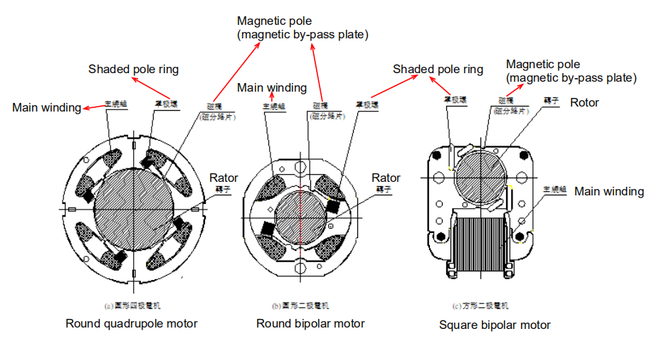
Figure 2 Three typical structures of shaded pole motor
5. Characteristic analysis
5.1 The efficiency of the shaded pole motor is relatively low, only between = (5 ~ 30)%, so it is mostly used in low-power drives.
5.2 The main and secondary phase currents of the shaded pole motor are not changed much, so the loss and temperature rise of the motor are mostly calculated based on the current when the motor is not moving. Therefore, the shaded pole motor will run when the rotor is locked without problems. Reliable operation Is its biggest advantage.
5.3 The starting and maximum torque multiples of shaded pole motors are specified as T * st = 0.3, T * max = 1.3, which are all too small. Therefore, shaded pole motors are mainly used in places where the starting torque is not required highly.
5.4 The shaded pole motor is specially designed to be able to rotate in two directions. The poles of such shaded pole motor are notched at both pole tips to place the shaded pole winding. Close a shaded pole winding as required, and the motor is Rotate in that direction.
5.5 The shaded pole motor can use step-down or tap speed regulation like a single-phase asynchronous motor. The motor with winding tap speed regulation is to add more speed coils to the windings of the motor. Connect these speed coils into the loop to connect to When the power supply goes up, it is as if a reactance is connected in series in the motor circuit to achieve the purpose of speed reduction.
6. The impact of structural factors on performance
6.1 Magnetic bridge (magnetic shunt)
The function of the magnetic bridge is to improve the magnetic flux distribution of the air gap and improve the mechanical characteristics of the motor. The introduction of the magnetic bridge is to intentionally increase the magnetic leakage between the poles. Although the excitation reactance is reduced, the excitation current is increased, and the maximum torque is reduced, but Because the magnetic flux Φb of the magnetic bridge does not link with the rotor turn, the mutual magnetic flux of the main and auxiliary windings is increased, and the air gap magnetic flux under one pole is changed from rectangular to trapezoidal, as shown in Figure 3d, thereby reducing the harmonic Wave component.
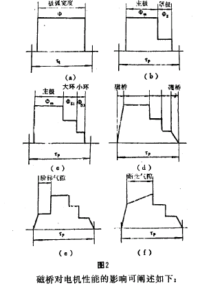
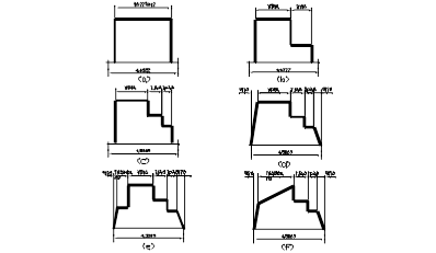
Figure 3
The influence of the magnetic bridge on the performance of the motor can be explained as follows:
6.1.1 Torque speed characteristic (T-n) curve
If the magnetic bridge is canceled, the magnetic flux leakage of the motor is reduced, the excitation reactance is increased, and the maximum torque Tmax of the motor is increased. However, because the air gap magnetic flux changes from trapezoidal to rectangular wave at this time, the harmonics increase, and thus the harmonics The increase of the torque component (mainly 3 times) reduces the T of the motor in the low- and medium-speed region and produces a significant depression. If the magnetic bridge is too wide, the magnetic leakage is too large, and the excitation reactance is reduced too much, although the harmonic When the wave is small, the Tn curve tends to be smooth, but according to the theorem of magnetic flux continuity, the air gap magnetic flux must be reduced. Not only does Tmax fall too much, but it also causes Tst to decrease, so it is also undesirable.
6.1.2 Tst Starting torque Tst
When the width of the magnetic bridge increases from 0, Tst increases faster first, and then gradually decreases after exceeding the maximum value (the optimal width at this time). The appropriate width of the magnetic bridge can increase Tst to 1.2 ~ when there is no magnetic bridge. 1.5 times.
It can be seen that the width of the magnetic bridge is important. In order to improve the magnetic potential waveform of the magnetic bridge without causing too much torque drop, the magnetic bridge is always designed to be in the state of super saturation of the magnetic density. Above 2.2T to limit its excessive magnetic flux leakage. For this reason, the initial design can take the following values: In Figure 2a, in order to maintain a certain rigidity, the magnetic shunt piece should not be too thin, so its axial direction can be reduced The length can be taken from 1/2 to 1/3 of the stacking length of the iron core. In Figure 2b, c, the two salient poles are connected by a pole tip to form one body. In order to ensure mechanical strength, it is obvious that the width of the pole tip cannot be too small, so it is used as Magnetic bridge is not feasible. For this reason, two symmetrical half-circle notches should be punched on the outside near the intersection axis, and the remaining width is used as the width of the magnetic bridge. Generally, half of the original width is taken because of the amplitude. It can be simply considered that the magnetic flux of each pole is evenly distributed throughout the pole, that is, the magnetic density in the pole is equal everywhere, and the magnetic density in the salient pole is always about 1.1 ~ 1.5T. If the width of the current magnetic bridge is 1/2 of the width of the pole tip, The magnetic density in the magnetic bridge is always above 2.2T.
Figure 5 shows the effect of the magnetic bridge width of a 8W square motor on mechanical characteristics.
6.2 Stepped air gap
The air gap is locally increased at the tip of the front pole, which is a stepped air gap. The larger the air gap, the larger the magnetic resistance. Since the magnetic field lines always try to shorten their path, the magnetic flux density in the stepped air gap is always smaller than the main air gap. From the electromagnetic ratio, the magnetic resistance of the stepped air gap is parallel to the magnetic resistance of the main air gap, the larger the magnetic resistance (resistance), the smaller the magnetic flux (current). Therefore, the use of the stepped axial clearance makes the air gap under one pole The magnetic flux changes from a rectangular wave to a stepped wave, as shown in Figure 3e, thereby reducing the harmonic component. The effect is better than the stepped air gap is a gradual air gap, because the length of the air gap gradually decreases from the front pole tip, thus Make the air gap pass wave into a slope shape, as shown in Figure 3f. The same function as the stepped air gap is to punch a closed long hole (circular motor) at the tip of the front pole or a long notch (square motor) on the outside, and make the air gap there by increasing the magnetic resistance of the local interval. The magnetic flux is smaller than the main air gap. However, because the gradual air gap is difficult to control and the punching hole is complicated, the mold is rarely used in practice.
The effect of the stepped air gap can not only improve the running performance, but also increase the starting torque. This is also caused by the characteristics of the magnetic field lines. At the junction of the stepped air gap and the main air gap, part of the magnetic flux starts from the stator on the main air gap. The rotor that reaches the stepped air gap, that means the magnetic field lines are bent toward the stepped air gap, makes the path longer and the magnetic resistance increases, and the rotor strives to be oriented with the minimum magnetic resistance of the magnetic circuit, which produces a Torque in the direction of the main air gap. Since the stepped air gap is located at the tip of the front pole, the torque is consistent with the direction of the rotating magnetic field.
The effect of the stepped air gap length δc and width (expressed in arc angle) θc on the Tn curve is as follows: δc does not change θc increases, or θc does not increase δc increases, the effect of the two is roughly the same. When δc (θc) increases , Tst and Tmax will increase, and because of the reduction of harmonic torque, the depression in the middle speed region decreases. However, too large δc (θc) will make Tmax decrease, and the characteristics will become softer, the slip of the operating point will increase, thus the loss will increase and the efficiency will decrease, but Tst will always be larger than that without stepped air gap. It can be seen that the values of δc and θc are very important. According to the data recommendation, the general values are around δc / δ = 2.5 ~ 3.5, θc / θp = 0.15 ~ 0.20.
6.3 Shaded pole ring
The role of the shaded pole ring is to cause the stator to generate a rotating magnetic field pulsating flux Φ. Without the shaded pole ring, only the main winding constitutes a single-winding motor, which generates a pulsating flux Φ in the air gap, as shown in Figure 3a, so The motor not only has no starting ability, but also has a small positive torque during operation. With the shaded pole ring, a part of Φm passes through the main air gap, and the other part Φ1 passes through the shaded pole region, thereby inducing current in the ring. Since the mask pole ring is an inductive component, the magnetic flux generated by the current in the ring is constant to prevent the change of Φ1, which causes the composite magnetic flux Φs of the mask pole region to lag behind the main magnetic flux Φm. In this way, there are two in the air gap Pulse beat flux Φm and Φs, as shown in Figure 3b. Because Φm and Φs have a phase difference in time, the two axes are staggered by another angle in space, thereby synthesizing a rotating magnetic field, generating starting torque, and starting and running the motor. However, since the angle θ between the two axes is less than 90 ° (there will be no Φs induced when θ = 90 °), the phase angle difference is also less than 90 ° (due to the resistance of the ring), and then Φs is less than Φm, so The combined magnetic field of the two is always an ellipse. And because Φs lags behind Φm, the rotation direction of the combined magnetic field always moves from the main pole to the shaded pole, that is, the motor cannot change its direction.
6.3.1 The ratio of shaded pole
The ratio of shaded pole Ks is defined as the percentage of the width of the magnetic pole in the shaded area to the width of the entire magnetic pole. Its size has a great influence on the performance of the motor. If the strength of the two pulse magnetic fields is the same, the smaller the Ks, the closer the angle θ between the two axes to 90 °, the smaller the ellipticity of the rotating magnetic field. However, since Φs is induced by the main winding, the smaller the Ks, the weaker the Φs, and the greater the ellipticity of the rotating magnetic field. From this, we know that there must be an optimal value of Ks, which weighs the angle between the two magnetic fields and The amplitude minimizes the ellipticity of the resultant magnetic field. Analysis and experiments show that the optimal shaded of the single-shaded ring motor is about 33% (that is, 1/3). At this time, Tmax and Tst are large, and the Tn curve is relatively flat. It is known from the experiment that when Ks is large, The mid-speed region of the Tn curve is very concave, but the Tst is low. When the limit Ks = 100%, the axis of the main and auxiliary windings coincide, which is equivalent to a shaded coil of transformer, the induced current in the auxiliary winding is the largest, and only the pulse magnetic field can be generated at this time, Tst = 0. When Ks is reduced, the change in Tmax is very small , Tst increases first, but the depression in the mid-speed region gradually increases; after less than 33%, Tst decreases, and when the limit Ks = 0, Tst = 0.
In the square iron core, due to the structural permission, two shaded rings are generally used to form a three-winding motor. In a three-phase symmetrical motor, each phase occupies 60 ° in a pole (180 ° electrical angle), that is, 60 ° phase band. Although it is impossible to achieve such a symmetrical distribution in a double-ring motor, the principle is the same, so the size of the ring taking the long and making up the shortcomings, the motor characteristics are obviously much better than the single ring: Tmax and Tst are increased, and the depression in the middle speed area is not serious. The experiment shows that in the double ring motor, when the main pole is about 110 °, the large ring is about 70 °. When the ring occupies about 40 ° in the 70 ° of the large ring, the motor characteristics are better. In other words, generally the large ring Ks1 = 40% and the small ring Ks2 = 22%.
As mentioned earlier, in order to obtain a large output torque, the synthetic magnetic field should be as close to a circle as possible. For this, Φm and Φs must have three conditions: the intensity is equal, the axis differs in space by 90 °, and the phase angle differs by 90 °. But this is contradictory: Since Φs is induced by the main winding flux Φ, the closer the angle between the main and auxiliary winding axes is 90 °, the smaller the mutual induction between the two, that is, the weaker Φs. At the limit position of 90 ° , The magnetic flux generated by the main winding cannot pass through the secondary winding, at this time, no current can be induced in the secondary winding, so that Φs is 0, and no torque can be generated. In order to produce a large secondary phase magnetism in a small ratio of shaded pole. It is completely necessary to use a magnetic bridge through Φs. Due to the existence of the magnetic bridge, a small part of the magnetic flux does not pass from one pole to the other through the air gap-rotor-air gap, but passes through the magnetic bridge, that is to say this small part of the magnetic flux is not linked with the rotor turns and is a leakage flux. In this way, because part of the magnetic flux in the shaded pole ring does not pass through the air gap, the magnetic resistance of the magnetic circuit of the shaded pole ring decreases, so that the magnetic flux Φs in the ring increases. It can also be understood that the magnetic bridge increases the main Mutual inductance between secondary windings, thereby increasing mutual inductance.
6.3.2 Shaded ring impedance
After the position of the shaded ring is determined, its own parameters have a great influence on the performance of the motor. The resistance rs of the cover ring has an optimal value for the starting torque. If rs is too large or too small, it will cause Tst to drop. In the motor, generally speaking, for thick copper wire or flat copper wire with only one turn, the rs is small, and the multi-turn type secondary winding wound with enameled wire is rs.The rs is too large. In this case, try to use a thicker gear. For a motor with a small rs, if it is replaced with an equal diameter wire such as brass, the electrical density will not change, and rs will be improved again, which is the performance of the motor. The increase in the leakage resistance of the cover ring xs will cause Tst to decrease. The end of shaded ring be as close to the lamination as possible, and its slot should be as close as possible to the inner diameter of the stator, in order to reduce its leakage flux.
6.3.3 The loss of shaded ring
Although the number of turns of the shaded ring is small, the induced potential in the ring is very small, but due to its extremely small impedance, the current in the ring is usually very large, resulting in large losses and high temperature, especially when blocked. Above 150 ° C (semiconductor point thermometer). Because the shaded ring is involved in the operation, the efficiency of the motor is very low, and the motor has the advantage of little change in the current of the machine when overloaded or even blocked, and is not prone to failure. If the design of the motor is unreasonable or the welding of the cover ring joint is not good, the heat of the shaded ring will be very serious, and even the welding point may be burned out, so that the motor cannot work normally, so the welding quality of the shaded ring must not be underestimated.
6.4 Main winding impedance (resistance r1 and leakage reactance x1)
The impedance of the main winding increases and the voltage drop on it increases. Because this is a useless consumption, the induced potential in the winding decreases. Since the induced potential is E1 =, when the power frequency f and the number of turns W1 remain unchanged, E1 The decrease means that the magnetic flux Φ of each pole decreases, and the motor output decreases. When the main winding resistance r1 is increased, the loss increases, the output decreases, and the temperature rise increases. However, when r1 increases, it is not a decrease in output It is equal to the increase in loss, but part of the loss increase is compensated by the power input, and part is compensated by the decrease in output. Therefore, when r1 is reduced (for example, the wire diameter is reduced by one gear) without reducing the number of turns, the For a fixed load, the input of the motor increases, the output decreases slightly, the speed decreases, the power factor rises slightly, and the temperature rise rises significantly. For the active load of wind blades, due to its power consumption is basically the same as The cube of the speed is proportional to the speed.When the speed is slightly reduced, the required torque drops a lot, so the motor behaves as the input is reduced, the output is slightly reduced, and the temperature rise is apparently increased.
For wind-blade active loads, because the power consumption is basically proportional to the cube of the speed, when the speed is slightly reduced, the required torque drops a lot, so the motor behaves as the input decreases, the output slightly decreases, the temperature rise is slightly increased. Therefore, for the fan motor, when the impedance protection is used, if the blocked temperature exceeds the standard, it can be considered to use a thin line, which can often solve the problem, and the impact on the speed and air volume is very small The stator leakage reactance includes slot leakage reactance xs, end leakage reactance xe, harmonic leakage reactance xδ and magnetic bridge leakage reactance xb. Reliable features tend to arrange the rated operating point near the maximum torque (especially the fan motor), where xb increases, the torque in the high-speed section will be significantly reduced, which is more disadvantageous than the rest of the leakage reactance. The thickness of the bridge must never be too thick, resulting in excessive magnetic leakage.
6.5 Rotor resistance r2
When the air gap magnetic field is circular and elliptical, the effect of r2 on torque is different.In a symmetrical motor, the air gap is a circular rotating magnetic field.When r2 increases, the slip rate of Tmax increases, and The value of Tmax is unchanged, the concave in the middle speed region decreases, and Tst increases. In the shaded pole motor, the magnetic potential of each winding cannot meet the three conditions of the circular magnetic field, so there is always a negative sequence component. When r2 changes The positive sequence torque and the negative sequence torque change according to the Tn curve of the symmetrical motor, so that the resultant torque, when r2 increases, not only the slip of Tmax increases, the depression decreases, but the Tmax value decreases, and Tst becomes very small, this situation can be illustrated by Figure 5.
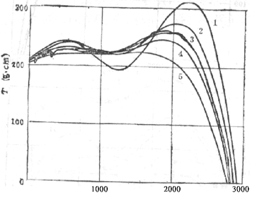
Figure 5 Effect of rotor resistance on mechanical characteristics (resistance increases with serial number)
In fact, there is an optimal value between Tst and r2. When r2 is at a certain value, Tst will get the maximum value. Therefore, it is better for shaded pole motor to reduce r2 as much as possible to obtain a large output. However, when the motor is adjusted If the speed is reduced, the entire Tn curve will decrease when the speed is reduced, which may cause the motor to crawl into a low speed and not reach the stable speed.
In small motors of a few watts, the rotor with fewer slots and shallow slots should be used as much as possible, which is great for the stability of cast aluminum, because the punching plate is originally very small, if there are many slots, the area of each slot is small, and if the slot is deep At one point, in particular, the bottom of the slot is prone to under-playing, or even broken rows, causing fluctuations in the quality of the motor.
6.6 Air gap length δ
For asynchronous motors, from the theoretical analysis of the sine wave, we can see that δ should be as small as possible. Because δ is small, the excitation reactance increases, thus the excitation current decreases, the no-load current is reduced, and the power factor increases and the efficiency increases. However, if δ is small, the precision of precision machining is high, and it is easy to increase the eccentric value (relative value), which makes it difficult to manufacture and operate. In addition, the air gap is not a sine wave, δ is smaller, the harmonic magnetic field and harmonic leakage reactance increase, resulting in the reduction of Tst, Ist and Tmax, and the increase of harmonic torque and additional losses, resulting in higher temperature rise and Loud noise. In shaded pole motors and other single-phase motors, it is beneficial to take δ larger than three-phase motors:
(a) The δ is larger, the leakage of the fixed rotor harmonic and the rotor chute are reduced. The result is that both Tst and Ist increase. Since the increase rate of Tst is greater than Ist, a suitably large δ can improve the starting performance of the motor . And because Tmax is proportional to the leakage resistance of the motor, the air gap increases and Tmax can increase.
(b) δ is larger, which reduces the harmonic flux amplitude of the stator and rotor.Since the stray loss is proportional to the square of the harmonic flux amplitude, a large δ can reduce the stray loss of the motor and make The efficiency has increased slightly. Of course, if δ is larger, not only does the no-load current increase and the power factor decreases, but also the load slip rate decreases (that is, the speed increases), and the load current also increases.The actual efficiency increase or decrease depends on which factor is leading.
(c) A larger δ can reduce the rotor surface loss, so that the rotor surface heat is greatly reduced, and the heat radiation to the stator is reduced, so the temperature rise should be reduced. However, if δ is increased too much, it will make the air gap required As the magnetic potential increases, this is bound to be supplemented by increasing the input current, thereby increasing the saturation of the motor, the copper consumption increases, and the temperature rises instead.
(d) δ is larger, even if the actual eccentricity value of the air gap is unchanged, its relative value (air gap unevenness) is smaller, which is especially important in single-phase motors. Because the air gap unevenness will cause single-phase motor There are different starting torques at different rotor positions, and reducing the unevenness of the air gap will reduce the fluctuation of Tst. And because the increase of δ weakens the higher harmonics, the additional torque is reduced, so that the Tmin of the motor increases , That is, the depression in the velocity region in the Tn curve decreases.
(e) The radial force generated by the interaction of any two harmonic magnetic fields is approximately proportional to δ2, so a larger δ can reduce noise and vibration. Theoretical analysis shows that when the air gap changes from δ1 to δ2, The corresponding bending of the electromagnetic noise level is approximately L1-L2 = 10 lg (δ2 / δ1) 4dB. Of course, due to the increase of no-load current and other reasons, it is actually less than the calculated value of the above formula.
Based on the above reasons, in single-phase motors, the air gap value is generally 0.05 ~ 0.1mm larger than that of three-phase motors. In general, when using ball bearings, 0.25 ~ 0.35mm is used. Due to the increase of δ by 10% ~ 20%, for the shaded pole motor, due to the more serious harmonic component in the air gap, δ should be larger, especially for square motors, the use of brackets is more likely to cause eccentricity δ is often taken to be 0.35 ~ 0.45 mm.
Basic knowledge of motor-Classification-Step motor
1. Definition
Step motor is a kind of special motor which can convert the electric pulse signal into corresponding angular displacement or linear displacement. A step motor and its matching driver make up a set of step motor system. Every time an electric pulse signal is input to the motor, the motor will rotate an angle. Its movement form is stepping type, so it is called step motor.
2. Features
1. High resolution and high accuracy positioning
Under the control of pulse signal, the angular displacement output is proportional to the number of input pulses, so as to realize the accuracy operation with the inherent step angle as the unit. The step distance error will not accumulate, and it is less affected by external conditions (such as voltage fluctuation, temperature change, etc.). Taking the 1.8°step angle motor as an example, its resolution per rotation can reach 1/200 (i.e. 1.8°/ 360°), 1 /400, and the accuracy of each step error can be controlled within ± 5%. If micro step subdivision drive is adopted, can achieved higher resolution and higher accuracy.
2. Simple system structure
Under the function of driver, step motor can convert digital pulse signal into angular displacement or linear displacement directly without motor speed or position detector, and can operate correctly according to pulse command.
3. Good performance control
The speed of the motor is synchronous with the frequency of the control pulse, so the speed of the motor can be adjusted in a wide range by changing the frequency of the control pulse. By controlling the pulse, we can get very low speed and high torque directly without the transition of gear reducer, so as to avoid the power loss and the influence of motion accuracy, and can quickly controllable starting, stop, reversion and shift.
4. With self-locked force
When the power supply is stopped, there is still a positioning torque. After the shutdown, it still keeps the state of power on for the winding. It has the self-locked ability and can keep the stop position without the brake system.
5. Longer use life
Using the electronic commutation, without carbon brush and commutator for mechanical friction, thus reducing friction and increasing the use life of the motor.
3. Application field
Based on the above features, step motor is widely used in various digital management motion control applications, such as printers, stage lights, ATM machines, security monitoring, industrial equipment, medical, textile machinery, automobile industry and other products and fields.
4. Basic Structure of step Motor
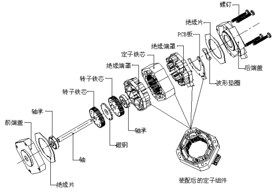
Installation instructions
1.Do not disassemble the motor.
2. The air gap between the stator and rotor of this kind of motor is very small. Do not knock the motor surface with heavy objects or make the motor fall to the ground.
3. Please select the appropriate mounting method (screw and penetration), as shown in the following figure;
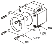
4. Select appropriate thickness of mounting plate to ensure mounting strength, Refer to the following table:
|
Motor model |
BJ28 |
BJ35 |
BJ39 |
BJ42 |
BJ54 |
BJ57 |
BJ85 |
BJ86 |
BJ110 |
|
Mounting plate thickness |
≥4mm |
≥5mm |
≥6mm |
≥8mm |
≥12mm |
||||
5. Working Principle
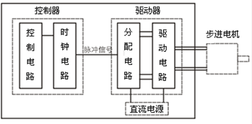
According to the external pulse, the step motor driver controls the winding of the step motor to be electrified in a certain time sequence, forward or reverse direction through the internal logic circuit, so as to make the motor run. Take the two-phase 1.8°step motor as an example:
1. According to the way of winding arrangements, there are generally two kinds of motors: four leads (bipolar) motor and six leads (Unipolar) motor.
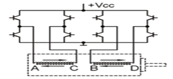
For four leads (bipolar) motor, the direction of power on of its winding shall be in the order of: AB-BC-CD-DA four states cycle by cycle for on-off change. Each time of change, the motor runs one step, i.e. rotates 1.8 °.
four leads (bipolar)
For six leads (Unipolar) motor, the direction of power on of its winding shall be in the order of: OA-OB-OC-OD four states cycle by cycle for on-off change. Each time of change, the motor runs one step, i.e. rotates 1.8 °.
four leads (bipolar)
For six leads (Unipolar) motor, the direction of power on of its winding shall be in the order of: OA-OB-OC-OD four states cycle by cycle for on-off change. Each time of change, the motor runs one step, i.e. rotates 1.8 °.
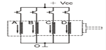
six leads (Unipolar)
2. Phase Order Diagram and Wiring Diagram
2.1 four leads (bipolar)
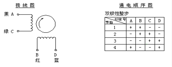
2.2 six leads (Unipolar)
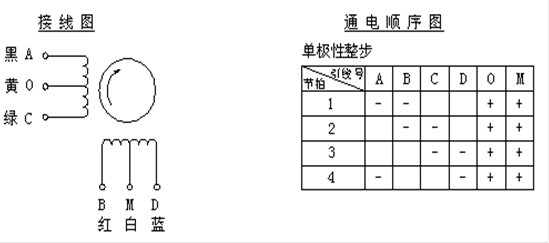
3. General Characteristics
| Item | Specification |
| Step Angle Accuracy | ±5% |
| Resistance Accuracy | ±10% |
| Inductance Accuracy | ±20% |
| Temperature Rise | ≤80℃(Rated Current) |
| Environmental temperature | -20℃~+50℃ |
| Insulation Resistance | 100MΩ Min. 500VDC |
| Withstanding Voltage | 500VAC·1min |
4. Naming Rule
BJ Y Z 42 D 15 - 01 V 01
① ② ③ ④ ⑤ ⑥ ⑦ ⑧ ⑨
① Step motor type
hybrid:BJ
permanent magnetic:PM
② Shape
Y:roundness
If there is no identification, it means the shape is square;
Just for the BJ motor, there is no logo on PM motor
③ Z:with gearbox
If there is no identification, it means it is without gearbox
④ Seat No.:overall dimension (mm), roundness means the outer diameter(mm)
⑤ Stepping angle
For BJ: C:0.9°;D:1.8°;E:0.6°;F:1.2°
G:3.6°;H:3.75°;K:5.625°
For PM: L:11.25°;P:15°;Q:0.72°;R:7.5°
⑥ Stator thickness:mm
⑦ Performance No.:01~99
Show the performance parameters of motor, such as current, torque and ect.
⑧ Motor polarity
N: unipolar and single out of shaft
M: unipolar and double out of shaft
V: bipolar and single out of shaft
W: bipolar and double out of shaft
⑨ Mechanical specification:01~99
Show the motor shaft extension, lead wire, screw and etc. mechanical parameters
Basic knowledge - Major categories - Brushess DC motor
1. Definition
Brushless motor refers to the motor without brush and commutator (or collector ring), also known as the non-commutator motor, which is composed of the main body of the motor and the driver. The brushless motor uses a transistor electronic commutation circuit to replace the brush and commutator mechanical commutation device to change the current direction, which overcomes the shortcomings of the short life of the traditional brush motor carbon brush. The permanent magnets of brushless DC motors are now mostly made of rare earth neodymium iron boron (Nd-Fe-B) materials with high magnetic energy levels. Therefore, the volume of the rare earth permanent magnet brushless motor is reduced by one frame size compared with the same capacity asynchronous motor.
2. Characteristics
1. It can replace brush motor speed regulation, frequency converter + frequency conversion motor speed regulation, asynchronous motor + speed reducer speed regulation;
2. It has the advantages of the traditional DC motor, and the carbon brush and slip ring structure are eliminated;
3. It can run at low speed and high power, and can save the reducer to directly drive a large load;
4. Small size, light weight and large output;
5. Excellent torque characteristics, good torque performance at medium and low speeds, large starting torque and small starting current;
6. Stepless speed regulation, wide speed regulation range, strong overload capacity;
7. Soft start and stop, good braking characteristics, can save the original mechanical brake or electromagnetic brake device;
8. High efficiency, the motor itself has no excitation loss and carbon brush loss, eliminating multi-stage deceleration consumption, and the comprehensive power saving rate can reach 20% ~ 60%.
9. High reliability, good stability, strong adaptability, simple repair and maintenance;
10. Resistant to bumpy vibration, low noise, small vibration, smooth operation and long life;
11. No sparks, especially suitable for explosive places, with explosion-proof type;
12. Trapezoidal wave magnetic field motor and sine wave magnetic field motor can be selected as required.
3. Application
Based on the above characteristics, brushless motors are widely used in various intelligent and automated applications, such as soft and hard disk drives, motorcycles, blowers, water pumps, aircraft models, household appliances, office automation, medical equipment, automobiles, etc.
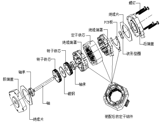
4. Construction of Brushless motor
The structure of brushless DC motor is mainly composed of three parts: motor body, position sensor and electronic switch circuit. The motor body is similar in structure to a permanent magnet synchronous motor, but without cage windings and other starting devices. The stator windings are generally made of multiple phases (three-phase, four-phase, no phase...), and the rotor is composed of permanent magnetic steel according to a certain number of pole pairs (2p = 2, 4, ...).
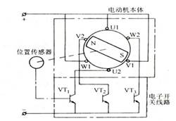
The main body of brushless DC motor is composed of permanent magnet rotor, multi-pole winding stator, position sensor and so on. The position sensor converts the current of the stator winding along a certain order according to the change of the rotor position (that is, detects the position of the rotor magnetic pole relative to the stator winding, and generates a position sensor signal at the determined position, which is processed by the signal conversion circuit To control the power switch circuit, switch the winding current according to a certain logical relationship). The working voltage of the stator winding is provided by the electronic switch circuit controlled by the output of the position sensor.
There are three types of position sensor: magnetic sensitive type, photoelectric type and electromagnetic type.
The brushless DC motor using a magnetosensitive position sensor, the magnetosensitive sensor device (such as Hall element, magnetodiode, magnetosensitive tube, magnetoresistor or special integrated circuit, etc.) is installed on the stator assembly, used to detect the change of the magnetic field generated when the permanent magnet and the rotor rotate.
A brushless DC motor with a photoelectric position sensor is equipped with a photoelectric sensor device at a certain position on the stator assembly. The rotor is equipped with a shading plate and the light source is a light-emitting diode or a small light bulb. When the rotor rotates, due to the effect of the shading plate, the photosensitive components on the stator will generate pulse signals intermittently at a certain frequency.
The brushless DC motor with electromagnetic position sensor is equipped with electromagnetic sensor components (such as coupling transformer, proximity switch, LC resonance circuit, etc.) on the stator assembly. When the position of the permanent magnet rotor changes, the electromagnetic effect will make the electromagnetic sensor Generate high frequency modulation signal (its amplitude changes with rotor position)
5. Working of Brushless motor
As we all know, the stator of a general permanent magnet DC motor is composed of permanent magnetic steel, and its main role is to generate a magnetic field in the air gap of the motor. The energized armature winding generates a reactive magnetic field. The energized armature winding generates a reactive magnetic field. Due to the commutation effect of the brushes, the directions of the two magnetic fields are always kept perpendicular to each other during the operation of the DC motor, thereby generating maximum torque and driving the motor to run continuously. In order to realize the brushless commutation of the DC brushless motor, the armature winding of the general DC motor is required to be placed on the stator, and the permanent magnet steel is placed on the rotor. But this is not enough, because the general DC power supply to the stator windings can only generate a fixed magnetic field, it can not interact with the permanent magnet magnetic field generated by the rotor magnet in motion to produce a single direction of torque To drive the rotor to rotate. Therefore, in addition to the stator and rotor composed of the motor body, the DC brushless motor also needs a commutation device composed of a position sensor, a control circuit, and a power logic switch, so that the stator winding generated by the brushless DC motor during operation The magnetic field and the permanent magnetic field generated by the rotating rotor magnet are always maintained at an electrical angle of (π / 2) rad in space.
6. General Characteristics
| Item | Specification |
| Speed accuracy | ±5% |
| Resistance accuracy | ±10% |
| Inductance accuracy | ±20% |
| Tempersture rise | ≤80℃(Rated current) |
| Ambient temperature | -30℃~+60℃ |
| Insulation resistance | 100MΩ Min. 500VDC |
| Hi-pot voltage | 500VAC·1min |
7. Naming rule
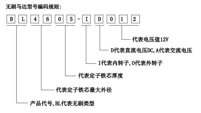
1. The Brushless motor is denoted by "BL"
2. It is expressed by the maximum outside diameter of the motor lamination
3. To the motor lamination stacked thickness value
4. "I" stands for inner rotor,"0" stands for external rotor
5. "D" indicates that DC voltage is used, "A" indicates that AC voltage is used
6. 012 represents the rated voltage of 12V
Basic knowledge-Major categories-Universal motor
1. Definition
The universal motor is a type of electric motor that can operate on either AC or DC power and uses an electromagnet as its stator to create its magnetic field. It is a commutated series-wound motor where the stator's field coils are connected in series with the rotor windings through a commutator.
2. Characteristics
1. Wide adaptability to external power supply
Whether AC or DC; 60Hz or 50 Hz; 12V, 24VDC or 110V, 220V, 240V; In short, it can be designed to accommodate any external power supply of the motor.
2. High speed, wide speed range
Universial motor’ s RPM range is 3000 to 40000RPM. A wide speed range can be obtained by using multiple taps on the same motor. These character is exactly need by those motor used in home appliances. For example, a vacuum cleaner needs the high speed to form a negative pressure inside and outside the container to generate suction.
3. Large starting torque and small size
When the load torque increases, the universial motor can adjust its rotation speed and current, to increase its torque.
3. Application
The universal motor has wide range of adjustable speed and large starting voltage make them useful for appliances such as electric power tool, kitchen appliances and application about hairdressing and floor caring
4. Construction of Universal motor
Components of Universal motor include stator, rotor, front&back bracket and cooling fan. Stator consists of stator core and the winding which install on polar head. The functions of stator are generate field flux and support the front&back brakcet. The rotor is composed of rotor core, shaft, armature winding and commutator. Its function is to ensure and generate a continuous electromagnetic torque, and transform electrical energy into mechanical energy. The front and back bracket support the armature and fix the connection of stator and rotor. Among above component, the rotating shaft, the front and back bracket should have enough strength, to prevent the armature and support resonance phenomenon, causing vibration and danger. Generally there will be rolling or sleeve bearing in the front and back bracket.

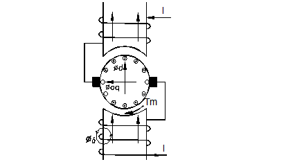
5. Working of universal motor
Like the basic working schematic show, when current flows in the upper stator winding, it produces an electromagnetic field with a certain direction; then it go into commutator (copper head) through carbon brush. The current is then divided into upper and lower parallel branches in the rotor winding. The rotor coil that conducts the flow is forced by an external magnetic field to rotate the rotor. The copper head keeps the current in the rotor symmetrical and continuous. The current finally flows out of the other carbon brush and into the lower stator.Since the upper and lower stator coils are wound in the same direction, the magnetic fields generated by the upper and lower stator are in the same direction, which has to be consistent
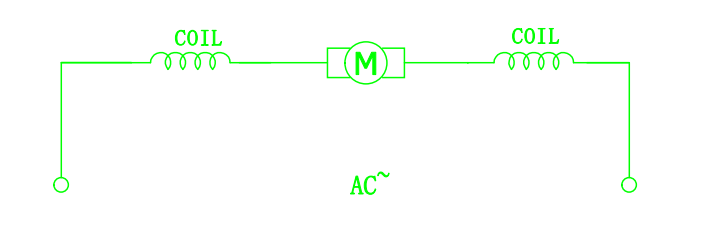
6. Wiring schematic diagram
7. Characteristics
In the work of single-phase universial motor, its load is not fixed at the rated point but changes. There are processes and changes such as starting, load, overload, blocking, shutdown, etc. The motor performance curve can fully describe the variation rule of parameters such as speed, efficiency, power factor, output power, input current and input power under rated voltage condition, when taking the output torque as the independent variable.
FIG. 3 is the test curve formed by fitting the data of input current, input power, output power and efficiency collected during the operation of the motor.
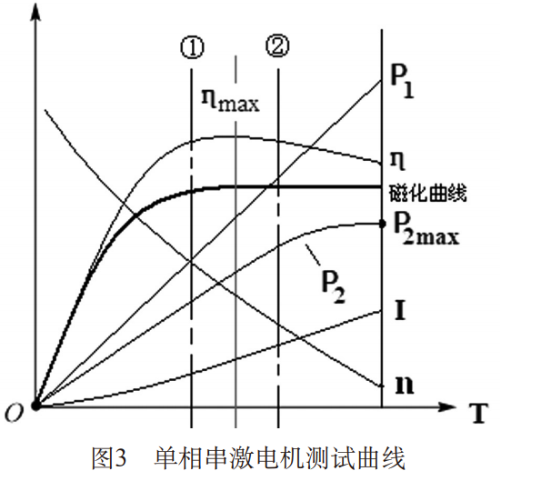
With the increase of load T, the working current I of the motor keeps increasing, and the input power P1 of the motor keeps increasing. As the working current of the motor increases, the iron core is magnetized and the stator excitation effect is continuously enhanced, the output power of the motor P2 increases. If only the influence of the iron core on the motor is considered, the motor efficiency increases gradually with the magnetization curve from the beginning of the magnetization section to the linear section. When the magnetization curve approaches saturation, the motor efficiency reaches the maximum. When the magnetization curve enters the saturation section, the magnetic energy reaches saturation, the output power of the motor P2 reaches the maximum, and the motor heat increases sharply and the efficiency decreases.
8. naming rule
XX XX XX X XXX
○1 ○2 ○3 ○4 ○5
○1 The universial motor is denoted by "HC"
○2 It is expressed by the maximum outside diameter of the motor lamination and rounded if there are decimal places
○3 To the motor lamination stacked thickness value, if there are decimal places will be rounded
○4 "M" indicates that alternating current is used
○5 The operating voltage is expressed by the Arabic number, and example 230 represents the rated voltage of 230V
For example:
HC8835M230 means the outer diameter of the motor is 88mm, the lamination stack thickness is 35mm, and the usage voltage is AC 230V
General Knowledge of the Motor
1. Definition of the motor
Motor refers to a device that converts electricity into power or electrical energy into mechanical energy.
Sometimes electrical input is abbreviated to input, and mechanical output is abbreviated to output. In the process of energy conversion, part of the input does not become power, but becomes heat, which is called loss.
a. The relationship between input power, output (also called power) and loss is as follows:
Input power = mechanical output + loss The unit of expressing these quantities is watt (W)
b. The definition formula of input power and mechanical output is expressed as follows:
Input power (W) = voltage (V) x current (A)
Mechanical output (W) = speed (rad / s) x torque (Nm)
c. The efficiency of the motor refers to the ratio of the mechanical output to the input power expressed in percentage (%).
Motor efficiency = output / input × 100%
Some of the losses are caused by mechanical reasons like friction, but the larger proportion is the loss in the copper wire and the loss in the iron core. The former is called copper loss, and the latter is called iron loss.
2. Components of the motor
2.1 The components of the motor mainly include five parts as shown in the below figure ① ~ ⑤
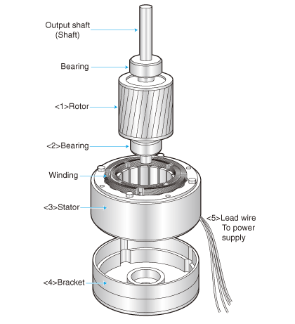
①Rotor or rotating body: the rotating part
②Bearing: the part that supports the rotor shaft (the shaft)
③ Stator: the part that generates the force that rotates the rotor
④Bracket or end plate: supports the bearing and becomes an integral part with the stator
⑤Wire: the stator of the wire connected to the drive circuit or power supply for the motor
2.2 Among the above constituent elements, the stator and rotor are more closely related to the basic classification of motor. The typical structure of the stator can be listed in the following four types.
A. Distributed winding stator
B. Concentrated winding stator
C. Induction stator
D. Permanent magnet stator
2.3 The rotor can be divided into 10 types.
A. Squirrel cage rotor
B. Salient pole cage rotor
C. Semi-hard magnetic steel rotor
D. Mild steel rotor
E. Salient pole type silicon steel rotor
F. Fine rack type mild steel rotor
G. Permanent magnet rotor
H. Induction rotor
I. Coil rotor
J. Commutator rotor
2.4 The main component material of the motor
A. Enameled wire
The material is generally copper, but aluminum is also used sometimes.
The wire is divided into a wire that supplies power from the power source to the motor and a coil formed inside the motor. From the point of view of the wire that generates a magnetic field, the part corresponding to the coil is also called enameled wire.
B. Iron core
The so-called iron core is a magnetic channel, as the literal meaning is, the material is iron. In addition, iron used to join two magnets by magnetic flux is generally called a yoke.
The iron used for the mechanism structure and the iron used for the core are different in the types of auxiliary components. The iron used for the mechanism structure contains carbon (C), and the iron used for the iron core is added with silicon (Si), which is also called silicon steel. In the motor, the iron core is divided into a stator iron core and a rotor iron core, and the magnetic circuit is formed by the gap between the two. The magnetic poles of the stator core constituting the excitation circuit of the electromagnet excitation type DC motor are excited by direct current. Therefore, the iron core does not need to have a laminated structure and use mild steel.
On the other hand, the magnetic flux of the rotor core constituting the armature circuit changes when it rotates, so a laminated core is used. In addition, permanent magnets are generally used for the magnetic poles of small DC motors. Since the excitation is performed by alternating current, the stator core of the synchronous motor, the stator of the induction motor and the iron core of the rotor are preferably laminated iron cores.
C. Insulator (material)
An insulator that interrupts the current to prevent the current from flowing outside the specified location. The material is an insulating material. Generally, rubber and polymer compounds called enamel / resin, paper, mica, glass fiber, etc. are used.
D. Permanent magnet
The most important material of the motor is the permanent magnet as the source of the magnetic field. It can also be called an alloy or oxide with iron as the main component.
3. Classification of motors (each category includes: definition, principle and structure, wiring, characteristics)
3.1. Shaded pole motor
3.2. Universal motor
3.3. Brushless DC motor
3.4. Hybrid stepper motor
3.5. Servo motor (servo system)
3.6. Pump motor
History of Electric Motor
In 1820, Hans Christian Ørsted, Danish, physicist and chemist; first to note magnetic effect of electric current.
In 1824, François Arago, French, physicist; showed people the rotating magnetic field which was the foundation of AC induction motor.
In 1831, Michael Faraday, British, scientist; discovered and investigated induction law and invented single pole DC motor.
In 1833, Hippolyte Pixii, French, instrument maker, built the first oscillating DC generator.
In 1833-1836, Otis, American; first design and invented ARBOR step motor.
In 1834, Moritz von Jacobi, German-Russian, engineer and physicist; made the first real useful rotary DC electrical motor.
In 1866, Werner Siemens, German, industrialist; invented the first self-excited motor
In 1867, James Clerk Maxwell, British, scientist; made a mathematical analysis of the phenomenon of self-excitation and published the first classic paper in the theory of electric machinery
In 1871, Van Meeren invented AC motor.
In 1879, Walter Baily, British; based on Arago's rotations, by manual switching on and off, developed the first primitive commutatorless induction motor.
In 1880, Thomas Edison, American; proposed to adopt laminated iron core, which reduced the loss of iron core and reduced the armature temperature rise.
In 1884, Manchis invented the compensating winding and the commutator pole, and the Brothers Hopkins invented the transformer.
In 1886, the Hopkins brothers established ohm's law of magnetic circuits, which enabled the design of magnetic circuits for electric motors.
In 1888, Galileo Ferraris, Italian, physicist and engineer; delivered a paper on “use AC to generate electric rotation”. At the same time, Tesla and Ferraris invented induction motor independently.
In 1889, Mikhail Dolivo-Dobrovolsky, Polish-Russian engineer, electrician, and inventor,steadfast in his promotion of three-phase development, invented the three-phase induction motor of both types cage-rotor and wound rotor with a starting rheostat, and the three-limb transformer
In 1891, Arnold established the theory of DC armature winding, and then the three-phase system was rapidly popularized
In 1899, when studying the armature reaction of salient pole synchronous motors, Brontel put forward the double reaction theory, which was later developed by Doherty, Nicol and Peck, and became the basis of modern synchronous motor theory
In 1920, A British invented step motor
Around 1940, a series of new control motors appeared, such as motor enlarger, AC tachometer generator, and loop conversion transformer, etc.
In 1970, the step motor research group of the university of Leeds in England pioneered a prototype of switched reluctance motor, which was the earliest research on switched reluctance motor
In 1978, Rexroth introduced permanent magnet AC servo motors and drive systems
In 1992, T.A. Lipo and other famous American electrical experts, first proposed the dual-salient permanent magnet motor


