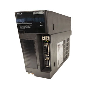
Basic function of servo DE6 bus series
|
Type
|
DE6 Bus series
|
|
Control power supply and main loop power supply
|
L: Single-phase or three-phase AC220V power supply;
B: Three-phase AC220V power supply; H: Three-phase AC380V power supply
Voltage fluctuation: -15 ~ + 10%, 50 / 60Hz
|
|
Environment
|
Temperature
|
Working:0~55℃ Storage: -40℃~80℃
|
|
Humidity
|
Not more than 90% (no frosting)
|
|
Air index
|
No dust in the electric cabinet (conductive medium such as iron powder)
|
|
Control Type
|
1:position control 2:SR trial operation 3:JOG operation
|
|
Outside I/O
|
1: Contracting brake
|
|
Encoder feedback
|
131072p/r(standard) 8388608 p/r(optional)
|
|
Communication method
|
1.MECHATROLINK II MECHATROLINK III Enter CAT
|
|
Load inertia
|
Less than 5times of motor inertia
|
|
Monitoring function
|
RPM, current position, command pulse accumulation, position deviation, motor current, running status, input and output terminals, etc.
|
|
Protection function
|
Over voltage, over current. Over load, wrong feedback, etc.
|
|
Warning function
|
When server is working abnormally, it is accompanied by alarm output, LED flashes, and red lights on
|
|
Gain adjustment
|
When motor running or stopped, the gain can be adjusted to match the performance of the motor
|
|
Matched Motor
|
See table2.2.1 2.2.2 2.2.3 2.2.4 2.2.5
|
MechatrolinkII/Ⅲ description of bus communication cable
1. MechatrolinkII/Ⅲ Bus connection type:
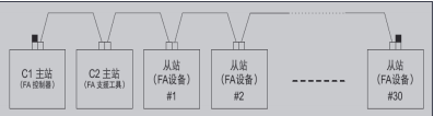
Note: 1.▇ connected to the C1 master station and terminal slave station indicates the termination resistance.
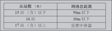
2:A repeater is used when the total distance of the network for 16 stations is more than 30m or the number of slave stations is greater than 17 stations
Note: In order to reduce the signal reflection of the terminal part, both ends of the network are connected with terminal connectors, but when the terminal (terminal resistance) is built in the C1 master station, the terminal connector can only be connected to the other terminal of the network; the resistance in the terminal connector is recommended as 130Ω 1 / 4W.
1. Mechatrolink II / Ⅲ Wiring Specifications regarding the total network distance and the distance between stations, perform network wiring according to the following specifications
When not using a repeater:
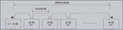
Note:
1.The total distance of the network refers to the maximum length of cable that the bus connected to the network
2.The distance between stations refers to the length of cable wiring between adjacent stations. Please ensure that the distance between stations is greater than 0.5m.
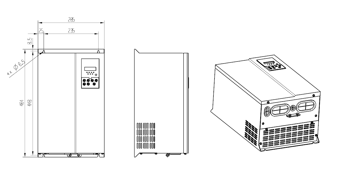
Appearance dimension
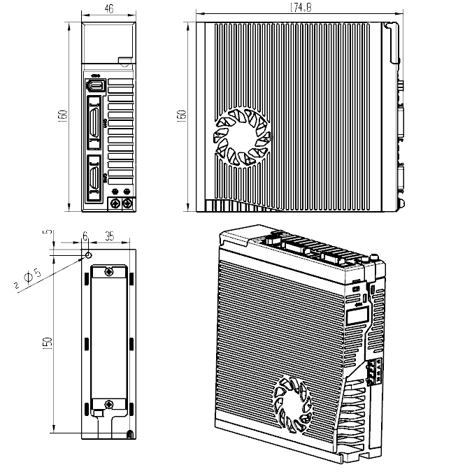
1.1.1 10A/22A/32A Appearance Dimension Drawing
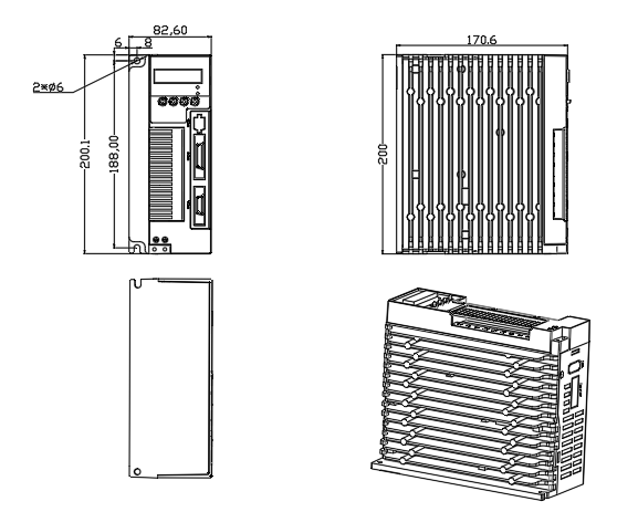
1.1.2 20A/30A Appearance Dimension Drawing
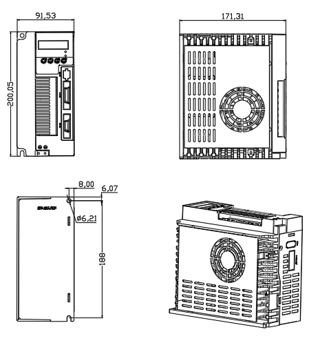
1.1.3 35A Appearance Dimension Drawing
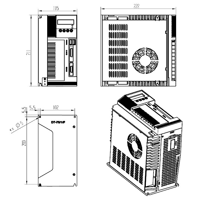
1.1.4 25A/50A/75A Appearance Dimension Drawing
1.2.1 100A Assembling Dimension Drawing
1.2.2 150A Assembling Dimension Drawing